
SELECTION CRITERIA
Selecting the most suitable seal for a rod or a piston is not easy, because some of the many factors that must be taken into account are often overlooked.
The seal must;
-Achieve the reguired degree of tightness.
-Be made from a material with adequate elasticity and dimensional stability to compensate of the cylinder inner diameter.
-Have good compatibility with the media throughout the working temperature range.
-Have good sliding feature, high abrasion resistance and be easy to install and replace.
-Material should not abrade or wear and allow particles to enter the system.
In addition to these there are other operating conditions which effect the analysis.
-System pressure. Seal must be able to operate at high and still be tight at low pressure.
-Location of the hydraulic equipment, outdoor and indoor.
-Working temperature range.
-Installation conditions.
-Length of stroke and frequency.
-Speed of movement.
-Expected friction and stick-slip behaviour.
-Operating and stationary periods.
-Material and roughness of the metal partners.
-Type and characteristics of seal material.
-Compatibility of the media with the material.
These conditions have an effect on the performance of the seal service life, leakage, friction, wear and reliability. These are important and influence selection of the optimum seal shape and material.
INSTALLATION ADVICES
To obtain the best performance the seal must be correctly installed, or it will not perform the required function or give the service life.
-Seals are not guide rings. For guiding moving parts and supporting side loads use a bearing of appropriate size and material.
-Seal materials can be damaged by side loads imposed on the rod and piston. For minimize this problem, it is recommended that the seal is positioned as near to the bearing as possible to obtain maximum protection.
-The sealing edges must be protected from damage when the seal is installed. All sharp edges of the housing must be removed and a chamfer provided at the edge of the rod and tube.
-When large radial section seals are fitted into a closed groove it will be easier if they are pre-heated in oil and carefully manipuladet to make them more flexible.
(i.e. Chevron seals)
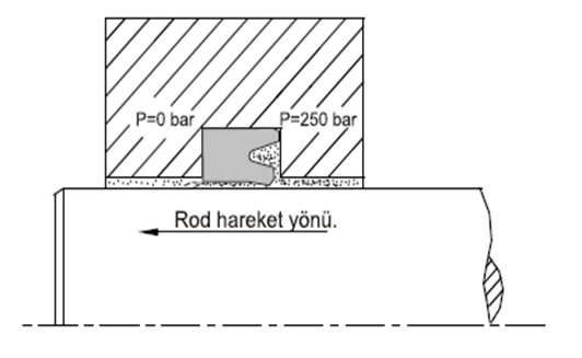
-The clearance between the moving parts should be kept to a minimum so that the extrusion gap will not cause damage to the seal.
(See maximum gap allowance diagram)
-Housing surfaces contacting the seal must not have sharp edges or peaks.
-A dirty rod surface retracting into the cylinder is the main cause of system contamination so a suitable scraper fing must be filled to remove the dirt before it can do any damage.
-Action should be taken to remove the air from the system. A particular attention is necessary when filling or venting the circuit.
-Make sure that no flow restrictions occur in the vicinity of seals. Otherwice it will lead to air being released from the fluid and damaging the seal.
-It is very important to respect the groove dimensions. Otherwice the seal has too less preload and can not 'breathe'.
-Ensure the seal is fitted in correct installation tools otherwise damage may occur. This may not apparent until the cylinder has been installed and in operation.
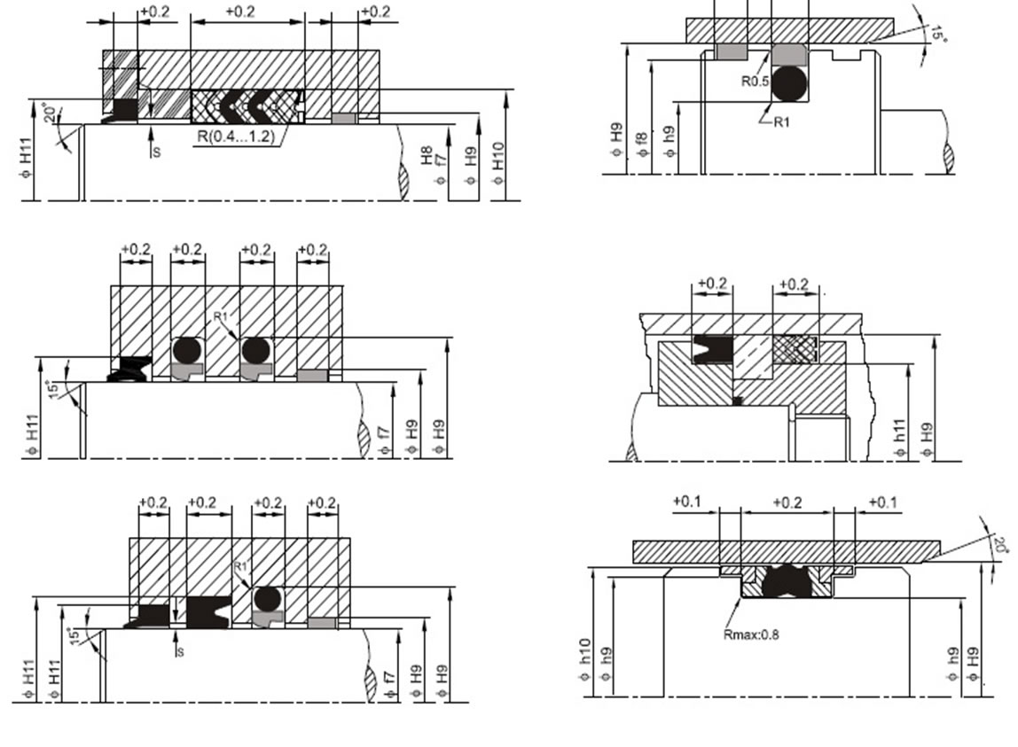
GENEL TOLERANCES
The service life of the seals mdepends on different factors as pressure, sliding speed, fluid's characteristics, quality of surface finishing. It is recommended to respect the dimensions and the tolerances of the rod, the piston and the cylinder.
The necessary tolerances for different applications are given below.
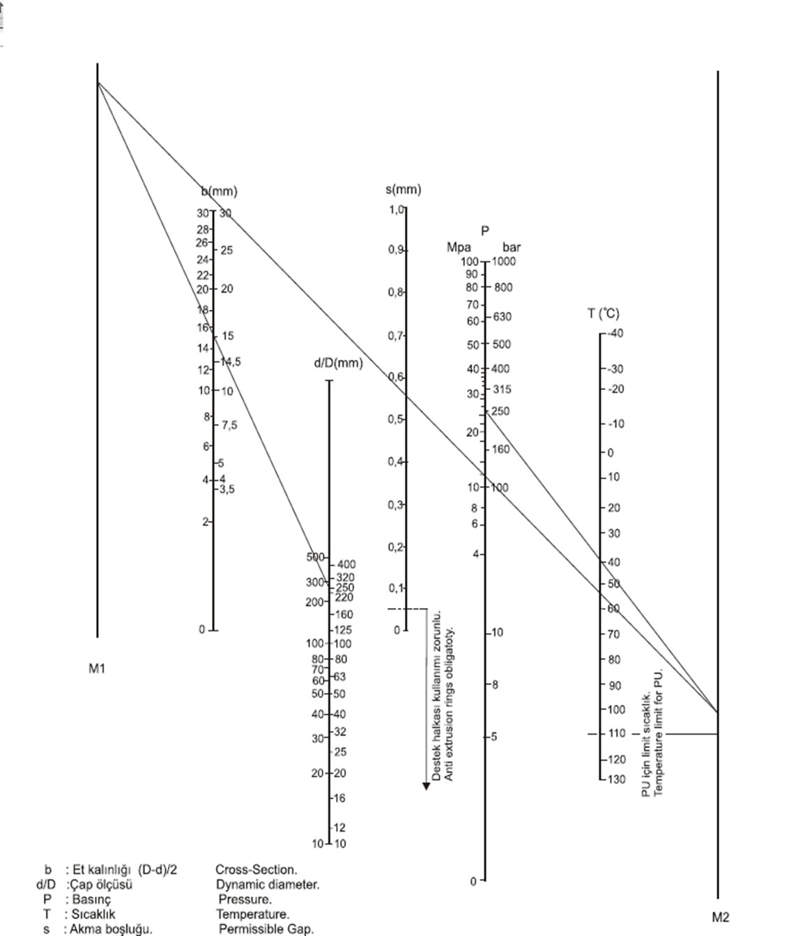
Örnek Uygulama:
Rod ölçüsü 250mm, sistem basıncı 250 bar, yağ sıcaklığı 40°C olan silindirde akma boşluğu (s)
ne olmalıdır?
1.Katalogtan P4-250X280X60 takım conta seçilir.
2.Profil değer (b) 15mm.ye çap eksenindeki 250 değerinden çizgi çizilerek M1 doğrusu kesilir.
3.Verilen basınç ve sıcaklık değerlerinden M2 doğrusu kesilir.
4.M1 ve M2 doğrularındaki kesişme noktaları birleştirilir.
5.Çizilen bu yeni doğrunun akma boşluğu (s) eksenini kestiği değer uygulanacak akma boşluğu değeridir. (0,55mm)
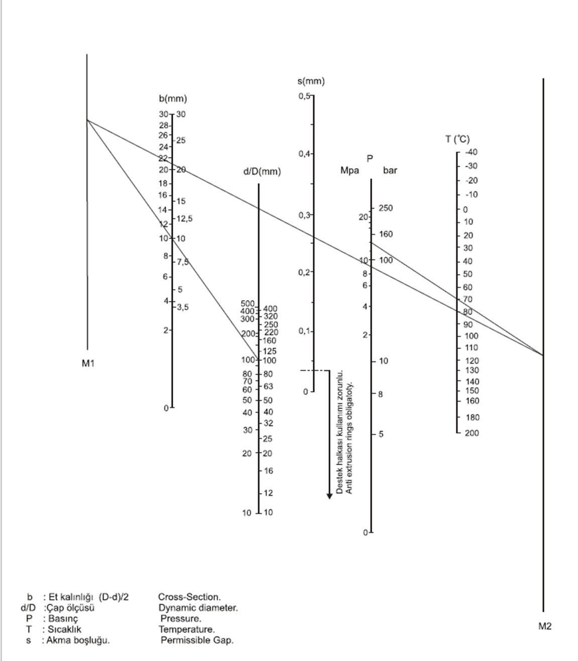
MAKSIMUM PERMISSIBLE GAP IN HYDRAULIC CYLINDERS.
FOR NBR AND FPM(Viton) U-CUPS.
APPLICATION PROBLEMS
Seals have contours similar to a disk. They slide a long surfaces and must cope with the problems coused by the sealing gap.
Destruction of a seal can be caused by several things but the foremost of these is wear. The material is abraided and the preload reduces until the seal leaks.
Other reasons include media contamination, air in the fluid, large extrusion gap, excessively rough surfaces, design and installation mistakes and termal and chemical effect of the media. All of these can result in the failure of the seal.
Wear by abrasion;
Excessive roughness is the major cause of abrasion and can be seen by the uniform roughening or smoothing of the surface. The seal will not perform the required function.
Damage by contamination;
Because filtration of the fluid is often neglected, particules find their way into the system and damage the seal. Also the wipers used on piston rods must be controlled carefully to avoid the penetration of the particules.
Effects of air in the fluid;
In a moleculer dissolved condition air is present in all hydraulic fluids, the gas molecules are mixed or attached to the oil molecules. In this form the air does not have any effect on the fluid. When the pressure is changed, the air is carried a long in the form of bubbles.
-Jet effect:
If the pressurized fluid contains undissolved air, when the pressure drops the bubbles are released and they damage the seal surface by creating a jet cutting effect and affect also the metal surfaces. (Piston rod)
-Diesel effect:
The pressure changes on the hydraulic cylinder occurs an increase of energy. Air is compressed at high speed and rapidly heats to a point where ignition will take place in the air-oil mixture. We can imagine this effect with ideal gase equation. For example:On 150 bars pressure, in 0,25 s. compression time the temperature can be increase up to 450°C. The result of this, is diesel explosion and than the guide ring and the seal will be burned and damaged. During sealing, teflon materials permit the passage of the gas and prevent the accumulation of the gas near of the sealing element. Sealing elements produced with teflon materials are not also so affected by diesel effect.
Cavitation
When pressurized fluid flows through a throttling line, the speed of flow increase leads to a decrease of the static pressure which may continue until a vacuum is reached. The result is a separation of air of the fluid and the formation of bubbles.
Drag pressure
On axial sliding cylinders if small tolerances are used at the front of the sealing element, the fluid will be pumped on the same direction. This may occur very high pressure and the sealing element may be destroyed.
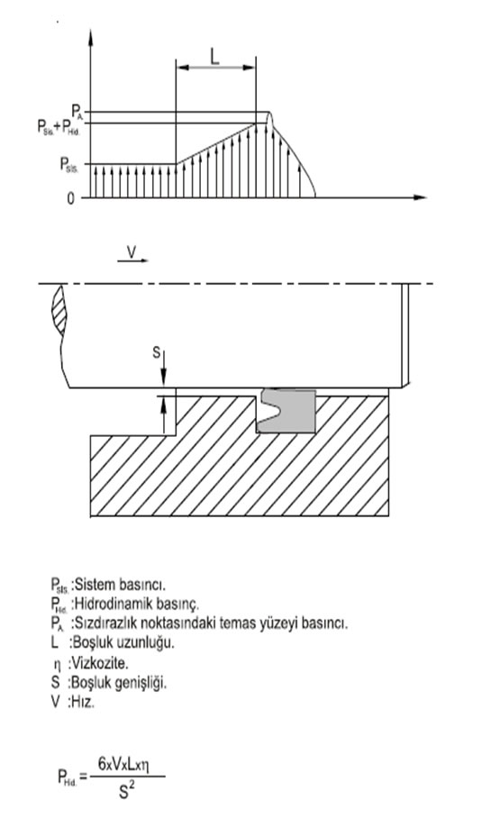
As seen on the equation, the drag pressure is directly proportional with the speed, the viscosity and the gap length and it is inversely proportional with the gap width square. If it is necessary to use a guide ring at the front of the seal, using long a guide ring may occur problems on the systems which are working with high viscosity and high speed. To solve the problem by enlarging the gap length is absolutely wrong. This may occur misalingments and the service life of the seal will diminish. The solution is to use angled cutted strips or guide rings and to increase the bearing gap. This will protect the seal from the jet effect. Another solution is to use a spiral groove at the front of the seal when metal guiding element is used.